 The handling and guiding methods of carbon fibers to prevent filament damage or to maintain fiber width is often overlooked. However, it is an extremely important factor in carbon fiber production and downstream processing using carbon fiber and other high-performance fibers.
Redirection with sharp angles, use of guides without proper surface finish, excessive tension, static contact points: these are all factors that can induce damage to the filaments in the carbon fiber tow. Broken filaments not only degrade the strength of the carbon fiber, but also cause issues in processing leading to production downtime.
Broken filaments accumulate on rotating parts and will accumulate beyond containment, which not only needs an operator to intervene but can stop production or create defects in the product.
Fiber width can also be compromised when the proper guide elements or proper alignment methods are not used. Fibers can become narrower when false twists are induced, or if guide flanges physically case a fiber to narrow down. In some cases, the lack of sizing in the fiber can have negative effects on the fiber width. When using low sizing content fiber or un-sized fibers, the need to use of proper guiding elements is magnified greatly.
The main reason proper assessments are not made for fiber damage caused by inadequate handling is that there have been no quantitative means to measure fiber damage. Similarly, tools to maintain or monitor fiber width have not available. Read more to find out about tools to accomplish this and some analyzation studies.
Tools for measuring filament damage and width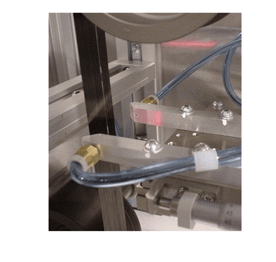
The CFA analyzers are made specifically to measure filament damage in the fiber. They are sensitive enough to measure a single carbon fiber filament breakage. The CFA can output a filament damage report in real time so that the certain area on the tow or timing of the damage of the fiber can be pinpointed. Reports are available in .csv format for easy analyzation. Other data such as fiber width, fiber spreadability, friction coefficient, and other parameters can also be collected with add-on modules.
These units can be used in-line of a process to determine the cause of fiber damage. They can also be used off-line for quality control purpose to monitor batches of fiber. It is also a common tool for R&D: for compatibility experiments using different fiber coating/sizing or to test newly developed fibers.
To learn more, visit the carbon fiber analyzer page here.
Filament damage study example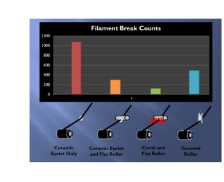
An example study using the CFA-Lite unit is shown below:
Using a commercially available 12K carbon fiber, 4 types of guiding configurations were used to redirect the fiber at a 45-degree angle:
- Ceramic eyelet only
- Ceramic eyelet and flat roller
- Comb and flat roller
- Grooved roller
The filament damage was recorded for a 5-minute period at 5 m/min line speed, so filament damage on a section of 25 meters was performed for each configuration.
This resulted in the below:
(a) Ceramic eyelet only = 1000+ breaks
(b) Ceramic eyelet and flat roller = 300+ breaks
(c) Comb and flat roller = 100+ breaks
(d) Grooved roller = 500+ breaks
So, in this case, it was obvious that the “ceramic eyelet only” was not a preferred method of fiber redirection, and other configurations would be better in terms of fiber damage reduction.
Filament spreadability study example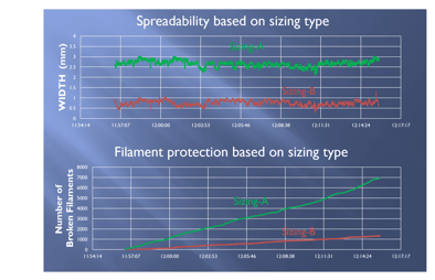
Another example study using the CFA-Lite unit is shown here:
Using a un-sized carbon fiber, we wanted to try new sizing formulations A and B which are both compatible with the resin matrix we intend to use.
Sizing-A and sizing-B were applied to the same un-sized carbon fiber and sent through a series of static spreader bars, and monitored with the CFA-Lite unit.
The chart on the top shows the width of the carbon fiber after the spreader bars, and the chart on the bottom shows the number of broken filaments detected after the spreader bars.
As the data shows, sizing-A appears to enable the fiber to be spread to wider widths compared to sizing-B. However, on the other hand it does appear that sizing-A does not protect the fiber as well as sizing-B. This type of analysis aids the carbon fiber or sizing formula manufacturer with useful data to determine the pros and cons of each type of sizing formula.
Self-aligning guide rollers to prevent fiber width variation
 In carbon fiber production or composite processes which require fiber handling, rollers with flanges are commonly used to redirect or guide fibers throughout the process.
The fiber may wander toward the flange and become narrow, or in some cases flip over to create a false twist. This is not ideal for many processes as the fiber width variation increases and may degrade the fiber or the final product.
The self-aligning guide roller is a flanged roller which automatically centers the fiber to the middle of the roller, and prevents the fiber from hitting the flange, even if it may wander from the upstream process.
These rollers can be placed in certain areas of the process to prevent the fiber from hitting the flange and maintaining the intended width.
Not exactly sure what type of analyzation tool you need, or have a custom parameter that you would like to analyze? Contact our experienced engineers for custom solutions tailored to your particular needs.