The handling and guiding methods of carbon fibers
to prevent filament damage is often overlooked. However, it is an extremely important factor in carbon fiber production and downstream processes using carbon fiber.
Redirection with sharp angles, use of guides without proper surface finish, excessive tension, static contact points: these are all factors that can induce damage to the filaments in the carbon fiber tow. Broken filaments not only degrade the strength of the carbon fiber, but also cause issues in processing leading to production downtime.
Broken filaments accumulate on rotating parts and will snowball into a mess quickly, which not only needs an operator to intervene but can stop production or create defects in the product.
The main reason proper assessments are not made for fiber damage caused by inadequate handling is that there have been no quantitative means to measure fiber damage. Read more to find out about tools to accomplish this and some analyzation studies.
Tools for measuring filament damage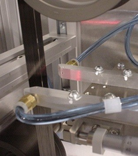
The CFA analyzers are made specifically to measure filament damage in the fiber. They are sensitive enough to detect a single carbon fiber filament breakage. The CFA can output a filament damage report in real time so that the certain area or timing of the damage of the fiber can be pinpointed exactly. Reports are available in .csv format for easy analyzation. Other data such as fiber width or friction coefficient can also be collected with advanced systems.
These units can be used in-line of a process to determine the cause of fiber damage. They can also be used off-line for quality control purpose. It is also a common tool for R&D: for compatibility experiments using different fiber coating/sizing or to test newly developed fibers.
To learn more, visit the carbon fiber analyzer page here.
Analysis example study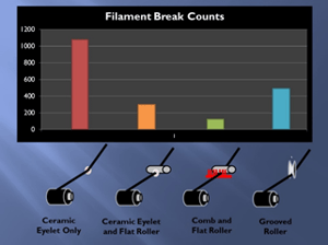
An example study using the CFA-Lite unit is shown below:
Using a commercially available 12K carbon fiber, 4 types of guiding configurations were used to redirect the fiber at a 45-degree angle:
- Ceramic eyelet only
- Ceramic eyelet and flat roller
- Comb and flat roller
- Grooved roller
The filament damage was recorded for a 5-minute period at 5 m/min line speed, so filament damage on a section of 25 meters was performed for each configuration.
This resulted in the below:
(a) Ceramic eyelet only = 1000+ breaks
(b) Ceramic eyelet and flat roller = 300+ breaks
(c) Comb and flat roller = 100+ breaks
(d) Grooved roller = 500+ breaks
So, in this case, it was obvious that the “ceramic eyelet only” was not a preferred method of fiber redirection, and other configurations would be better in terms of fiber damage reduction.
Not exactly sure what type of analyzation tool you need, or have a custom parameter that you would like to analyze? Contact our experienced engineers for custom solutions tailored to your particular needs.